You have found two sauna diagrams: one shows the inlet near the floor, the other above the heater. Do not choose at random. They may describe different ventilation systems and equipment requirements.
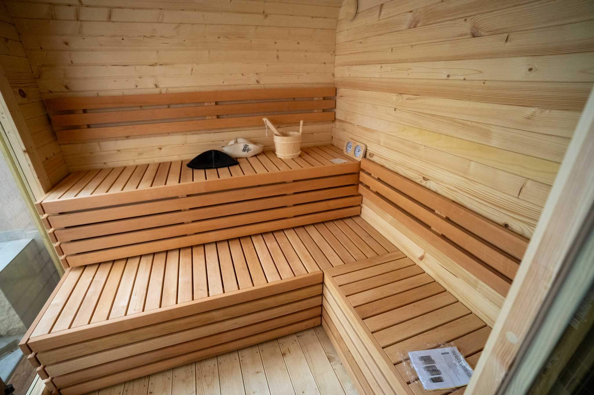
In an electric sauna, the air path must be planned together with the heater, temperature sensor and building ventilation. This article helps you check the design without turning a general diagram into instructions for drilling the cabin.
First: natural or mechanical ventilation?
Natural ventilation uses temperature and pressure differences to circulate air. In some layouts, the inlet is beneath or beside the heater. Operation also depends on where the air comes from and where it is exhausted.
Mechanical ventilation uses a fan or the building’s system. Some layouts bring fresh air in above the heater, mix it with heated air and extract it lower down in another part of the cabin. Exact positions remain those required by the manufacturer and design.
Technical documents do not all recommend the same solution. Some favour natural draught and require inlet and outlet to communicate with the same space; others explicitly describe mechanical ventilation. Do not combine an inlet position from one manual with an outlet from another.
Why does the sensor position matter?
Fresh air directed at the sensor can cool it and disrupt temperature control. Do not move the sensor to make room for a grille or cover it. Check inlet distances and mounting position in the control and heater manuals.
Before work begins, ask for the heater, sensor, benches, inlet and outlet to be marked on the same diagram. A photo of a grille without these reference points does not allow the solution to be checked.
What does ‘six air changes per hour’ mean?
It is a reference used in some electric sauna instructions. For a cabin with an internal volume of 8 m³, the indicative calculation is 8 × 6 = 48 m³/h.
The result alone does not select a fan or determine the grille diameter. Actual airflow depends on ducts, bends, grilles and pressure differences. A fan labelled 48 m³/h does not guarantee that flow in the installed system. Sizing must be checked for the actual route.
Is ventilation during sauna use the same as airing it afterwards?
Not always. Some cabins have a separate high-level opening for drying after use. Its operating position may differ from that used during heating and bathing. Do not close all grilles to retain heat or randomly leave an opening intended only for drying open.
After use, follow the cabin’s drying procedure. Leaving the door open may be part of it, but does not automatically replace the ventilation needed while the sauna is in use.
Five questions before approving installation
- Which ventilation system is specified, and where is it described in the manual?
- Which space does the air come from and return to?
- What is the design airflow and how will it be verified?
- Is the inlet far enough from the sensor?
- Which vent stays open during sauna use, and how should the cabin dry afterwards?
If the sauna heats unusually, thermal protection trips or the air becomes uncomfortable, stop using it and have the installation checked. Do not disable protections or copy the layout of a wood-fired sauna.
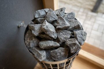
Send the NOMAD team the cabin plan and chosen equipment before making changes. For heater maintenance, see the guide to sauna stones.
Sources: documentation on natural and mechanical ventilation, sensors and drying; technical sauna construction guide — natural ventilation conditions. Also see sensor positioning instructions and documentation on airflow, inlets and drying. The airflow calculation is illustrative, not an installation design.